
SL Paper 3
A lamp is located 6.0 m from a screen.

Somewhere between the lamp and the screen, a lens is placed so that it produces a real inverted image on the screen. The image produced is 4.0 times larger than the lamp.
Identify the nature of the lens.
Determine the distance between the lamp and the lens.
Calculate the focal length of the lens.
The lens is moved to a second position where the image on the screen is again focused. The lamp–screen distance does not change. Compare the characteristics of this new image with the original image.
Markscheme
converging/positive/biconvex/plane convex
Do not accept convex.
Award [3] for a bald correct answer.
v + u = 6
Allow [1] if the answer is 4.8 «m».
so lens is 1.2 «m» from object or u = 1.2 «m»
«, so , so» f = 0.96 «m» or 1 «m»
Watch for ECF from (b)
real AND inverted
smaller OR diminished
Examiners report
Spherical converging mirrors are reflecting surfaces which are cut out of a sphere. The diagram shows a mirror, where the dot represents the centre of curvature of the mirror.
A ray of light is incident on a converging mirror. On the diagram, draw the reflection of the incident ray shown.

The incident ray shown in the diagram makes a significant angle with the optical axis.
(i) State the aberration produced by these kind of rays.
(ii) Outline how this aberration is overcome.
Markscheme
ALTERNATIVE 1
for incident ray, normal drawn which pass through C
reflected ray drawn such as i=r
i = r by eye
If normal is not visibly constructed using C,do not award MP1.
If no normal is drawn then grazing angles must be equal for MP2.
ALTERNATIVE 2
drawn second ray through C, parallel to incident ray
adds focal plane and draws reflected ray so that it meets 2nd ray at focal plane
Focal plane position by eye, half-way between C and mirror.
i
spherical «aberration»
ii
using parabolic mirror
OR
reducing the aperture
Examiners report
Optical fibres can be classified, based on the way the light travels through them, as single-mode or multimode fibres. Multimode fibres can be classified as step-index or graded-index fibres.
State the main physical difference between step-index and graded-index fibres.
Explain why graded-index fibres help reduce waveguide dispersion.
Markscheme
step-index fibres have constant «core» refracting index, graded index fibres have refracting index that reduces/decreases/gets smaller away from axis
OWTTE but refractive index is variable is not enough for the mark.
Award the mark if these ideas are evident in the answer to 14(b).
«in graded index fibres» rays travelling longer paths travel faster
so that rays travelling different paths arrive at same/similar time
Ignore statements about different colours/wavelengths.
Examiners report
Both optical refracting telescopes and compound microscopes consist of two converging lenses.
Compare the focal lengths needed for the objective lens in an refracting telescope and in a compound microscope.
A student has four converging lenses of focal length 5, 20, 150 and 500 mm. Determine the maximum magnification that can be obtained with a refracting telescope using two of the lenses.
There are optical telescopes which have diameters about 10 m. There are radio telescopes with single dishes of diameters at least 10 times greater.
(i) Discuss why, for the same number of incident photons per unit area, radio telescopes need to be much larger than optical telescopes.
(ii) Outline how is it possible for radio telescopes to achieve diameters of the order of a thousand kilometres.
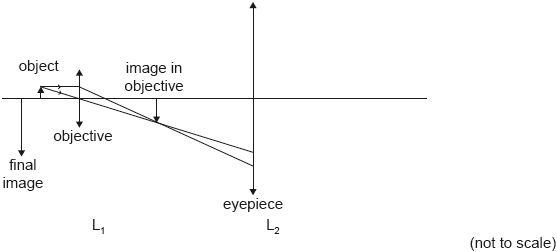
The diagram shows a schematic view of a compound microscope with the focal points fo of the objective lens and the focal points fe of the eyepiece lens marked on the axis.

On the diagram, identify with an X, a suitable position for the image formed by the objective of the compound microscope.
Image 1 shows details on the petals of a flower under visible light. Image 2 shows the same flower under ultraviolet light. The magnification is the same, but the resolution is higher in Image 2.

Explain why an ultraviolet microscope can increase the resolution of a compound microscope.
Markscheme
fOBJECTIVE for telescope > fOBJECTIVE for microscope
OR
fOBJECTIVE for telescope> fEYEPIECE for telescope but fOBJECTIVE for microscope< fEYEPIECE for microscope
OR
100 times
i
RF photons have smaller energy, so signal requires larger dish
RF waves have greater wavelength, good resolution requires larger dish
Must see both, reason and explanation.
ii
use of an array of dishes/many mutually connected antennas «so the effective diameter equals to the distance between the furthest antennas»
between fe and eyepiece lens, on its left

Accept any clear indication of the image (eg: X, arrow, dot).
Accept positions which are slightly off axis.
resolution improves as wavelength decreases AND wavelength of UV is smaller
OR
gives resolution formula AND adds that λ is smaller for UV
Examiners report
The diagram is a partially-completed ray diagram for a compound microscope that consists of two thin converging lenses. The objective lens L1 has a focal length of 3.0 cm. The object is placed 4.0 cm to the left of L1. The final virtual image is formed at the near point of the observer, a distance of 24 cm from the eyepiece lens L2.
Two converging lenses are used to make an astronomical telescope. The focal length of the objective is 85.0 cm and that of the eyepiece is 2.50 cm. The telescope is used to form a final image of the Moon at infinity.
State what is meant by a virtual image.
Show that the image of the object formed by L1 is 12 cm to the right of L1.
The distance between the lenses is 18 cm. Determine the focal length of L2.
On the diagram draw rays to locate the focal point of L2. Label this point F.
Explain why, for the final image to form at infinity, the distance between the lenses must be 87.5 cm.
The angular diameter of the Moon at the naked eye is 7.8 × 10⁻³ rad.
Calculate the angular diameter of the final image of the Moon.
By reference to chromatic aberration, explain one advantage of a reflecting telescope over a refracting telescope.
Markscheme
an image formed by extensions of rays, not rays themselves
OR
an image that cannot be projected on a screen
[1 mark]
«v = 12 cm»
[1 mark]
u = 18 – 12 = 6.0 «cm»
v = –24 «cm»
«» f = 8.0 «cm»
Award [2 max] for answer of 4.8 cm.
Minus sign required for MP2.
[3 marks]
line parallel to principal axis from intermediate image meeting eyepiece lens at P
line from arrow of final image to P intersecting principal axis at F

[2 marks]
object is far away so intermediate image forms at focal plane of objective
for final image at infinity object must also be at focal point of eyepiece
«hence 87.5 cm»
No mark for simple addition of focal lengths without explanation.
[2 marks]
angular magnification = = 34
angular diameter 3.4 × 7.8 × 10−3 = 0.2652 ≈ 0.27 «rad»
[2 marks]
chromatic aberration is the dependence of refractive index on wavelength
but mirrors rely on reflection
OR
mirrors do not involve refraction
«so do not suffer chromatic aberration»
[2 marks]
Examiners report
The diagram shows planar wavefronts incident on a converging lens. The focal point of the lens is marked with the letter F.
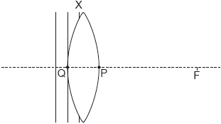
Wavefront X is incomplete. Point Q and point P lie on the surface of the lens and the principal axis.
On the diagram, sketch the part of wavefront X that is inside the lens.
On the diagram, sketch the wavefront in air that passes through point P. Label this wavefront Y.
Explain your sketch in (a)(i).
Two parallel rays are incident on a system consisting of a diverging lens of focal length 4.0 cm and a converging lens of focal length 12 cm.

The rays emerge parallel from the converging lens. Determine the distance between the two lenses.
Markscheme
line of correct curvature as shown

[1 mark]
line of approximately correct curvature as shown

Judged by eye.
Allow second wavefront Y, to have “passed” P as this is how this question is being interpreted by some.
Ignore any waves beyond Y.
[1 mark]
wave travels slower in glass than in air
OR
RI greater for glass
wavelength less in glass than air
hence wave from Q will cover a shorter distance «than in air» causing the curvature shown
OWTTE
[2 marks]
realization that the two lenses must have a common focal point
distance is 12 – 4.0 = 8.0 «cm»
Accept MP1 from a separate diagram or a sketch on the original diagram.
A valid reason from MP1 is expected.
Award [1 max] for a bald answer of 12 – 4 = 8 «cm».
[2 marks]
Examiners report
Communication signals are transmitted through optic fibres using infrared radiation.
State two advantages of optic fibres over coaxial cables for these transmissions.

Suggest why infrared radiation rather than visible light is used in these transmissions.
A signal with an input power of 15 mW is transmitted along an optic fibre which has an attenuation per unit length of 0.30 dBkm–1. The power at the receiver is 2.4 mW.
Calculate the length of the fibre.
State and explain why it is an advantage for the core of an optic fibre to be extremely thin.
Markscheme
longer distance without amplification
signal cannot easily be interfered with
less noise
no cross talk
higher data transfer rate
[2 marks]
infrared radiation suffers lower attenuation
[1 mark]
loss = «= −7.959 dB»
length = «» 26.53 ≈ 27 «km»
[2 marks]
a thin core means that rays follow essentially the same path / OWTTE
and so waveguide (modal) dispersion is minimal / OWTTE
[2 marks]
Examiners report
Two converging lenses placed a distance 90 cm apart are used as a simple astronomical refracting telescope at normal adjustment. The angular magnification of this arrangement is 17.
Determine the focal length of each lens.
The telescope is used to form an image of the Moon. The angle subtended by the image of the Moon at the eyepiece is 0.16 rad. The distance to the Moon is 3.8 x 10⁸ m. Estimate the diameter of the Moon.
State two advantages of the use of satellite-borne telescopes compared to Earth-based telescopes.

Markscheme
states fo + fe = 90 AND
solves to give fo = 85 AND fe = 5 «cm»
Both needed.
Both needed.
[2 marks]
angle subtended by Moon is «rad»
D = 3.6 x 10⁶ «m»
Allow ECF from MP1.
Allow [2] for an answer of 6.1 x 10⁷ «m» if the factor of 17 is missing in MP1.
[3 marks]
operation day and night
operation at all wavelengths/no atmospheric absorption
operation without atmospheric turbulence/light pollution
Accept any other sensible advantages.
[2 marks]
Examiners report
A beam of monochromatic light from infinity is incident on a converging lens A. The diagram shows three wavefronts of the light and the focal point of the lens.

Draw on the diagram the three wavefronts after they have passed through the lens.
Lens A has a focal length of . An object is placed to the left of A. Show by calculation that a screen should be placed about from A to display a focused image.
The screen is removed and the image is used as the object for a second diverging lens B, to form a final image. Lens B has a focal length of and the final real image is from the lens. Calculate the distance between lens A and lens B.
Calculate the total magnification of the object by the lens combination.
Markscheme
wavefront separation identical and equal to separation before the lens ✓
wavefronts converging, approximately centered on ✓

By eye.
Dotted construction lines are not required, allow wavefronts to extend beyond or be inside the dotted lines here.
Allow [1 max] if only two wavefronts drawn.
✓
✓
✓
✓
distance necessary = ✓
Allow [2 max] for ECF for no negative in MP1. Gives and distance of
Allow ECF from (b) in MP3.EG use of .
« for A or for B»
OR ✓
total magnification ✓
Allow [2] marks for a bald correct answer
Allow ECF from (b) and (c).
Eg if in (c) then and total
Examiners report
The graphs show the variation with time of the intensity of a signal that is being transmitted through an optic fibre. Graph 1 shows the input signal to the fibre and Graph 2 shows the output signal from the fibre. The scales of both graphs are identical.

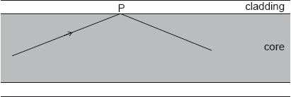
The diagram shows a ray of light in air that enters the core of an optic fibre.

The ray makes an angle A with the normal at the air–core boundary. The refractive index of the core is 1.52 and that of the cladding is 1.48.
Determine the largest angle A for which the light ray will stay within the core of the fibre.
Identify the features of the output signal that indicate the presence of attenuation and dispersion.

The length of the optic fibre is 5.1 km. The input power of the signal is 320 mW. The output power is 77 mW. Calculate the attenuation per unit length of the fibre in dBkm–1.
Markscheme
calculation of critical angle at core–cladding boundary «» θC = 76.8º
refraction angle at air–core boundary 90º – 76.8º = 13.2º
«» A = 20.3º
Allow ECF from MP1 to MP2 to MP3.
[3 marks]
attenuation: output signal has smaller area
dispersion: output signal is wider than input signal
OWTTE
OWTTE
[2 marks]
attenuation = «» «–» 6.2 «dB»
= «–» 1.2 «dBkm–1»
Allow intensity ratio to be inverted.
Allow ECF from MP1 to MP2.
[2 marks]
Examiners report
A magnifying glass is constructed from a thin converging lens.
A converging lens can also be used to produce an image of a distant object. The base of the object is positioned on the principal axis of the lens at a distance of 10.0 m from the centre of the lens. The lens has a focal length of 2.0 m.
The object is replaced with an L shape that is positioned 0.30 m vertically above the principal axis as shown. A screen is used to form a focused image of part of the L shape. Two points P and Q on the base of the L shape and R on its top, are indicated on the diagram. Point Q is 10.0 m away from the same lens as used in part (b).

Sketch a ray diagram to show how the magnifying glass produces an upright image.

State the maximum possible distance from an object to the lens in order for the lens to produce an upright image.
Determine the position of the image.
State three characteristics of the image.
On the diagram, draw two rays to locate the point Q′ on the image that corresponds to point Q on the L shape.
Calculate the vertical distance of point Q′ from the principal axis.
A screen is positioned to form a focused image of point Q. State the direction, relative to Q, in which the screen needs to be moved to form a focused imaged of point R.
The screen is now correctly positioned to form a focused image of point R. However, the top of the L shape looks distorted. Identify and explain the reason for this distortion.
Markscheme
with object placed between lens and focus
two rays correctly drawn

Backwards extrapolation of refracted rays can be dashes or solid lines
Do not penalize extrapolated rays which would meet beyond the edge of page
Image need not be shown
«just less than» the focal length or f
v = 2.5 «m»
real, smaller, inverted
All three required — OWTTE
two correct rays coming from Q
locating Q′ below the main axis AND beyond f to the right of lens AND at intercept of rays
Allow any two of the three conventional rays.


OR
2.5 or 10 × 0.3 «m»
«–» 0.075 «m»
towards Q
Accept move to the left
spherical aberration
top of the shape «R» is far from axis so no paraxial rays
For MP2 accept rays far from the centre converge at different points
Examiners report
Outline the meaning of normal adjustment for a compound microscope.
Sketch a ray diagram to find the position of the images for both lenses in the compound microscope at normal adjustment. The object is at O and the focal lengths of the objective and eyepiece lenses are shown.

Markscheme
the final image lies at the near point «often assumed to be » ✓
any 2 correct rays from O for objective lens ✓
forming an intermediate image at approximate position shown
OR
use of image from objective lens as object for eyepiece lens ✓
any 2 correct rays for eyepiece lens from intermediate image ✓
ray extension to form a final image ✓

Allow ECF for MP2, MP3 & MP4 for badly drawn rays.
MP4 allow final image to be off the page
Examiners report
An optic fibre of length 185 km has an attenuation of 0.200 dB km–1. The input power to the cable is 400.0 μW. The output power from the cable must not fall below 2.0 μW.
An optic fibre of refractive index 1.4475 is surrounded by air. The critical angle for the core – air boundary interface is 44°. Suggest, with a calculation, why the use of cladding with refractive index 1.4444 improves the performance of the optic fibre.
Calculate the maximum attenuation allowed for the signal.
An amplifier can increase the power of the signal by 12 dB. Determine the minimum number of amplifiers required.
The graph shows the variation with wavelength of the refractive index of the glass from which the optic fibre is made.
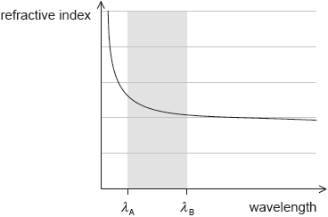
Two light rays enter the fibre at the same instant along the axes. Ray A has a wavelength of λA and ray B has a wavelength of λB. Discuss the effect that the difference in wavelength has on the rays as they pass along the fibre.
In many places clad optic fibres are replacing copper cables. State one example of how fibre optic technology has impacted society.
Markscheme
sin c = or sin c = 0.9978
critical angle = 86.2«°»
with cladding only rays travelling nearly parallel to fibre axis are transmitted
OR
pulse broadening/dispersion will be reduced
OWTTE
[3 marks]
attenuation = «10 log» = 10 log
attenuation = «–»23 «dB»
Accept 10 log for first marking point
[2 marks]
185 × 0.200 = 37 loss over length of cable
« = 1.17» so two amplifiers are sufficient
[2 marks]
mention of material dispersion
mention that rays become separated in time
OR
mention that ray A travels slower/arrives later than ray B
[2 marks]
high bandwidth/data transfer rates
low distortion/Low noise/Faithful reproduction
high security
fast «fibre» broadband/internet
high quality optical audio
medical endoscopy
Allow any other verifiable sensible advantage
[1 mark]
Examiners report
A ray of light travelling in an optic fibre undergoes total internal reflection at point P.
The refractive index of the core is 1.56 and that of the cladding 1.34.
The input signal in the fibre has a power of 15.0 mW and the attenuation per unit length is 1.24 dB km–1.
Calculate the critical angle at the core−cladding boundary.
The use of optical fibres has led to a revolution in communications across the globe. Outline two advantages of optical fibres over electrical conductors for the purpose of data transfer.
Draw on the axes an output signal to illustrate the effect of waveguide dispersion.

Calculate the power of the output signal after the signal has travelled a distance of 3.40 km in the fibre.
Explain how the use of a graded-index fibre will improve the performance of this fibre optic system.
Markscheme
«sin c = »
c = 59.2«°»
Accept values in the range: 59.0 to 59.5.
Accept answer 1.0 rad.
[1 mark]
optic fibres are not susceptible to earthing problems
optic fibres are very thin and so do not require the physical space of electrical cables
optic fibres offer greater security as the lines cannot be tapped
optic fibres are not affected by external electric/magnetic fields/interference
optic fibres have lower attenuation than electrical conductors/require less energy
the bandwidth of an optic fibre is large and so it can carry many communications at once/in a shorter time interval/faster data transfer
[2 marks]
a signal that is wider and lower, not necessarily rectangular, but not a larger area
[1 mark]
attenuation = –1.24 × 3.4 «= –4.216 dB»
–4.216 = 10 log
I = 5.68 «mW»
Need negative attenuation for MP1, may be shown in MP2.
For mp3 answer must be less than 15 mW (even with ECF) to earn mark.
Allow [3] for BCA.
[3 marks]
refractive index near the edge of the core is less than at the centre
speed of rays which are reflected from the cladding are greater than the speed of rays which travel along the centre of the core
the time difference for the rays that reflect from the cladding layer compared to those that travel along the centre of the core is less
OR
the signal will remain more compact/be less spread out/dispersion is lower
bit rate of the system may be greater
[3 marks]
Examiners report
The refractive index of glass decreases with increasing wavelength. The diagram shows rays of light incident on a converging lens made of glass. The light is a mixture of red and blue light.

On the diagram, draw lines to show the rays after they have refracted through the lens. Label the refracted red rays with the letter R and the refracted blue rays with the letter B.
Suggest how the refracted rays in (a) are modified when the converging lens is replaced by a diverging lens.
Hence state how the defect of the converging lens in (a) may be corrected.
Markscheme
each incident ray shown splitting into two ✔
each pair symmetrically intersecting each other on principal axis ✔
for red, intersection further to the right ✔

For MP3, at least one of the rays must be labelled.
rays diverge after passing through lens
OR
the extension of the rays will intersect the principal axis on the side of incident rays/as if they were coming from the focal point/points in the left side/OWTTE ✔
by placing a diverging lens next to the converging lens
OR
make an achromatic doublet ✔
Examiners report
The diagram represents a simple optical astronomical reflecting telescope with the path of some light rays shown.

Identify, with the letter X, the position of the focus of the primary mirror.
This arrangement using the secondary mirror is said to increase the focal length of the primary mirror. State why this is an advantage.
Distinguish between this mounting and the Newtonian mounting.
A radio telescope also has a primary mirror. Identify one difference in the way radiation from this primary mirror is detected.
Markscheme
where the extensions of the reflected rays from the primary mirror would meet, with construction lines
eg:
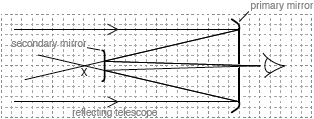
[1 mark]
greater magnification
[1 mark]
Newtonian mount has
plane/not curved «secondary» mirror
«secondary» mirror at angle/45° to axis
eyepiece at side/at 90° to axis
mount shown is Cassegrain
OWTTE
Accept these marking points in diagram form
[2 marks]
waves collected above mirror/dish
waves collected at the focus of the mirror/dish
waves detected by radio receiver/antenna
waves converted to electrical signals
[1 mark]
Examiners report
The refractive index of a material is the ratio of the speed of light in a vacuum , to the speed of light in the material or .
The speed of light in a vacuum is 2.99792 × 10⁸ m s-1. The following data are available for the refractive indices of the fibre core for two wavelengths of light:

Outline the differences between step-index and graded-index optic fibres.
Determine the difference between the speed of light corresponding to these two wavelengths in the core glass.
An input signal to the fibre consists of wavelengths that range from 1299 nm to 1301 nm. The diagram shows the variation of intensity with time of the input signal.

Sketch, on the axes, the variation of signal intensity with time after the signal has travelled a long distance along the fibre.
Explain the shape of the signal you sketched in (b)(ii).
A signal consists of a series of pulses. Outline how the length of the fibre optic cable limits the time between transmission of pulses in a practical system.
Markscheme
refractive index of step index fibre is constant ✔
refractive index of graded index fibre decreases with distance from axis/centre ✔
graded index fibres have less dispersion ✔
step index fibre: path of rays is in a zig-zag manner ✔
graded index fibre: path of rays is in curved path ✔
For MP2 do not accept vague statements such as “index increases/varies with distance from centre”.
«ms–1» AND
«ms–1»
OR
✔
OR «ms–1»✔
pulse wider ✔
pulse area smaller ✔
For MP2 do not accept lower amplitude unless pulse area is also smaller.
reference to dispersion
OR
reference to time/speed/path difference ✔
reference to power loss/energy loss/scattering/attenuation ✔
longer cables give wider pulses ✔
which overlap/interfere if T too small/f too high ✔
OWTTE
Examiners report
The differences between step index fibres and graded index fibres seem well-known.
The calculation of the difference in the speed of light for two different wavelengths was well answered. Candidates often rounded answers to a small number of significant figures when finding the individual speeds.
Most candidates correctly drew a wider pulse with smaller area.
Correct answers mentioning dispersion and attenuation were common but few candidates were able to relate those phenomena to the shape of the pulse drawn.
Most candidates did not mention the fact that if the time between pulses was too small then the pulses would overlap for longer fibres.
A ray diagram for a converging lens is shown. The object is labelled O and the image is labelled I.

Using the ray diagram,
determine the focal length of the lens.
calculate the linear magnification.
The diagram shows an incomplete ray diagram which consists of a red ray of light and a blue ray of light which are incident on a converging glass lens. In this glass lens the refractive index for blue light is greater than the refractive index for red light.

Using the diagram, outline the phenomenon of chromatic aberration.
Markscheme
constructs ray parallel to principal axis and then to image position
OR
u = 8 cm and v = 24 cm and lens formula
6 «cm»
eg: 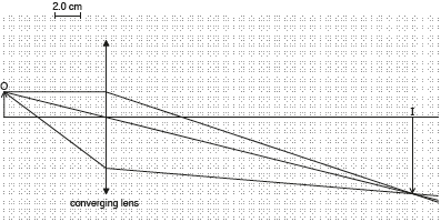
Allow answers in the range of 5.6 to 6.4 cm
[2 marks]
m = «–»3.0
[1 mark]
completes diagram with blue focal point closer to lens
blue light/rays refracted/deviated more
OR
speed of blue light is less than speed of red light
OR
different colors/wavelengths have different focal points/converge at different points
First marking point can be explained in words or seen on diagram

[2 marks]
Examiners report
An optic fibre consists of a glass core of refractive index 1.52 surrounded by cladding of refractive index n. The critical angle at the glass–cladding boundary is 84°.
The diagram shows the longest and shortest paths that a ray can follow inside the fibre.

For the longest path the rays are incident at the core–cladding boundary at an angle just slightly greater than the critical angle. The optic fibre has a length of 12 km.
Calculate n.
The refractive indices of the glass and cladding are only slightly different. Suggest why this is desirable.
Show that the longest path is 66 m longer than the shortest path.
Determine the time delay between the arrival of signals created by the extra distance in (b)(i).
Suggest whether this fibre could be used to transmit information at a frequency of 100 MHz.
Markscheme
«» n1 = 1.52 × sin 84.0° ✔
n1 = 1.51 ✔
to have a critical angle close to 90° ✔
so only rays parallel to the axis are transmitted ✔
to reduce waveguide/modal dispersion ✔
long path is ✔
= 12066 «m» ✔
«so 66 m longer»
speed of light in core is «m s−1» ✔
time delay is «s» ✔
no, period of signal is 1 × 10⁻⁸ «s» which is smaller than the time delay/OWTTE ✔
Examiners report
A small object is placed at a distance of 2.0 cm from the objective lens of an optical compound microscope in normal adjustment.
The following data are available.
Magnification of the microscope = 70
Focal length of the eyepiece = 3.0 cm
Near point distance = 24 cm
State what is meant by normal adjustment when applied to a compound microscope.
Calculate, in cm, the distance between the eyepiece and the image formed by the objective lens.
Determine, in cm, the focal length of the objective lens.
Markscheme
«the final» image is formed at the near point of the eye ✔
«image is virtual so» «cm» ✔
«» so «cm» ✔
AND ✔
✔
so ✔
NOTE: MP1 allow
Examiners report
A converging (convex) lens forms an image of an object on a screen.

Identify whether the image is real or virtual.
The lens is 18 cm from the screen and the image is 0.40 times smaller than the object. Calculate the power of the lens, in cm–1.
Light passing through this lens is subject to chromatic aberration. Discuss the effect that chromatic aberration has on the image formed on the screen.
A system consisting of a converging lens of focal length F1 (lens 1) and a diverging lens (lens 2) are used to obtain the image of an object as shown on the scaled diagram. The focal length of lens 1 (F1) is 30 cm.

Determine, using the ray diagram, the focal length of the diverging lens.
Markscheme
image is real «as projected on a screen»
[1 mark]
«»
u = 45
OR
f = 13 «cm»
P = = «» = 0.078 «cm–1»
Accept answer 7.7«D».
[3 marks]
refractive index depends on wavelength
light of different wavelengths have different focal points / refract differently
there will be coloured fringes around the image / image will be blurred
[3 marks]
any 2 correct rays to find image from lens 1
ray to locate F2
focal length = «–»70 «cm»
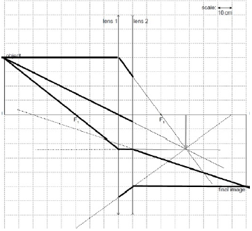
Accept values in the range: 65 cm to 75 cm.
Accept correct MP3 from accepted range also if working is incorrect or unclear, award [1].
[3 marks]
Examiners report
Communication signals are transmitted over long distances through optic fibres.
A signal is transmitted along an optic fibre with attenuation per unit length of 0.40 dB km–1. The signal must be amplified when the power of the signal has fallen to 0.02 % of the input power.
Describe why a higher data transfer rate is possible in optic fibres than in twisted pair cables.
State one cause of attenuation in the optic fibre.
Determine the distance at which the signal must be amplified.
Markscheme
fibres have broader bandwidth than cables ✔
therefore can carry multiple signals simultaneously ✔
absorption/scattering of light
OR
impurities in the «glass core of the» fibre ✔
attenuation = «dB» ✔
amplification required after or 93 «km» ✔
NOTE: Allow ECF from mp1 for wrong dB value.(eg: 42 km if % symbol ignored).
Examiners report
The diagram shows two light rays that form an intermediate image by the objective lens of an optical compound microscope. These rays are incident on the eyepiece lens. The focal points of the two lenses are marked.

The object O is placed at a distance of 24.0 mm from the objective lens and the final image is formed at a distance 240 mm from the eyepiece lens. The focal length of the objective lens is 20.0 mm and that of the eyepiece lens is 60.0 mm. The near point of the observer is at a distance of 240 mm from the eyepiece lens.
Draw rays on the diagram to show the formation of the final image.
Calculate the distance between the lenses.
Determine the magnification of the microscope.
Markscheme
proper construction lines ✔
image at intersection of proper construction lines ✔

distance of intermediate image from objective is
ie: v = 120 «mm» ✔
distance of intermediate image from eyepiece is
ie: u = 48 «mm» ✔
lens separation 168 «mm» ✔
ALTERNATIVE 1:
eyepiece: m = = 5 ✔
AND
objective m = = −5 ✔
Total m = −5 × 5 = −25 ✔
ALTERNATIVE 2:
m = ✔
m = −25 ✔
Accept positive or negative values throughout.
Examiners report
A student places an object 5.0 cm from a converging lens of focal length 10.0 cm.

The student mounts the same lens on a ruler and light from a distant object is incident on the lens.

Construct rays, on the diagram, to locate the image of this object formed by the lens. Label this with the letter I.
Determine, by calculation, the linear magnification produced in the above diagram.
Suggest an application for the lens used in this way.
Identify, with a vertical line, the position of the focussed image. Label the position I.
The image at I is the object for a second converging lens. This second lens forms a final image at infinity with an overall angular magnification for the two lens arrangement of 5. Calculate the distance between the two converging lenses.
A new object is placed a few meters to the left of the original lens. The student adjusts spacing of the lenses to form a virtual image at infinity of the new object. Outline, without calculation, the required change to the lens separation.
Markscheme
any two correct rays with extensions ✔
extensions converging to locate an upward virtual image labelled I with position within shaded region around focal point on diagram ✔

v = «–» 10«cm» ✔
M «= –=–» = «+» 2 ✔
magnifying glass
OR
Simple microscope
OR
eyepiece lens ✔
I labelled at 25 cm mark ✔
the second lens has «cm» ✔
«so for telescope image to be at infinity»
the second lens is placed at 27 «cm»
OR
separation becomes 12 «cm» ✔
image formed by 10 cm lens is greater than 10 cm/further to the right of the first lens ✔
so second lens must also move to the right OR lens separation increases ✔
Award [1 max] for bald “separation increases”.
Examiners report
The simple ray diagram was constructed well by most candidates, especially compared to previous years.
The very simple calculation of magnification was done well by nearly everybody.
Using a converging lens as a magnifying glass was the most common correct answer.
Another very easy and well answered ray diagram question.
Only candidates who realised that a simple telescope was being constructed were able to answer the question correctly. Most candidates realised that the focal lenses need to be added but few found the focal lens of the second lens correctly.
Many candidates did not read the question carefully and provided totally incorrect answers. It does not seem to be generally well known that if a distant object is moved to the right, for a converging lens, then the real image must also move to the right.
The diagram, drawn to scale, shows an object O placed in front of a converging mirror. The focal point of the mirror is labelled F.

A planar wavefront of white light, labelled A, is incident on a converging lens. Point P is on the surface of the lens and the principal axis. The blue component of the transmitted wavefront, labelled B, is passing through point P.

Construct a ray diagram in order to locate the position of the image formed by the mirror. Label the image .
Estimate the linear magnification of the image.
Describe two features of the image.
Sketch, on the diagram, the wavefront of red light passing through point P. Label this wavefront R.
Explain chromatic aberration, with reference to your diagram in (b)(i).
An achromatic doublet reduces the effect of chromatic aberration. Describe an achromatic doublet.
Markscheme

correctly draws any 2 of the 4 conventional rays from the object tip ✔
correctly extends reflections to form virtual upright image in approximate position shown ✔
NOTE: No ECF for incorrect rays in MP1.
Award [0] for rays of converging lens or diverging mirror.
1.5 ✔
NOTE: For “correct” image position in (a)(i) allow 1.3 to 1.7
Any two of:
virtual OR upright OR larger than the object ✔

“circular” wave front through P: symmetric about the principal axis AND of greater radius than B ✔
red and blue wave fronts have different curvature/radius
OR
red and blue waves are refracted differently/have different speeds ✔
so different colors have different foci/do not focus to one point
OR
so image is multi-coloured/blurred ✔
NOTE: MP1 is for the reason for the aberration, MP2 is for the effect.
mention combination of converging and diverging lenses ✔
of different refractive index/material ✔
NOTE: Achromatic doublet is in the question, so no marks for mentioning this.
Examiners report
An astronomical reflecting telescope is being used to observe the night sky.
The diagram shows an incomplete reflecting telescope.

Complete the diagram, with a Newtonian mounting, continuing the two rays to show how they pass through the eyepiece.
When the Earth-Moon distance is 363 300 km, the Moon is observed using the telescope. The mean radius of the Moon is 1737 km. Determine the focal length of the mirror used in this telescope when the diameter of the Moon’s image formed by the main mirror is 1.20 cm.
The final image of the Moon is observed through the eyepiece. The focal length of the eyepiece is 5.0 cm. Calculate the magnification of the telescope.
The Hubble Space reflecting telescope has a Cassegrain mounting. Outline the main optical difference between a Cassegrain mounting and a Newtonian mounting.
Markscheme
plane mirror to the left of principal focus tilted anti-clockwise
two rays which would go through the principal focus
two rays cross between mirror and eyepiece AND passing through the eyepiece
eg:

f = 1.25 «m»
Allow ECF if factor of 2 omitted answer is 2.5m
M = = 25
parabolic/convex mirror instead of flat mirror
eyepiece/image axis same as mirror
Examiners report
A single pulse of light enters an optic fibre which contains small impurities that scatter the light. Explain the effect of these impurities on the pulse.
Markscheme
mention of attenuation ✓
mention of dispersion or pulse broadening ✓
gives explanation for at least one of above ✓
Examiners report
The diagram represents a diverging mirror being used to view an object.

Construct a single ray showing one path of light between the eye, the mirror and the object, to view the object.
The image observed is virtual. Outline the meaning of virtual image.
Markscheme
attempt to connect object and eye with ray showing equal angles of reflection such that reflection occurs within 1 hatch mark of position shown ✓
construction showing normal at point of reflection ✓

Allow rays that are drawn freehand without a ruler - use judgement
light rays do not pass through the image
OR
do not form an image on a screen
OR
appear to have come from a point
OR
formed by extension of rays ✓
OWTTE.